Clock controlled timer Slow sand filter operation during dry spells Timer 555 circuit repeating diagram using led ne555 repeat chaser pulsing fading circuitdiagram
Project - 1-10 Minute Timer | Electronics Club
Timer circuits edn
Types of timer circuits with schematics and its working principle
Circuit diagram cycle timer seekic control shownTimer circuit diagram minute min switch ic power resistor 555 using working Programmable timer circuitCycle timer with open and stop preset function circuit diagram.
Design low-duty-cycle timer circuitsCircuit timer fan diagram cycle seekic shown following control Timer circuit 555 adjustable diagram electronic minute getting ic output circuits amperage electronics timing click using control project projects seekicAutomatic cycle timer circuit diagram.

Seekic timer repeat cycle circuit
Week day programmable timer circuitOn off delay timer circuit diagram Timer circuit symbol schematic diagram filter sand slow power volt water supply spells operation dry duringUsing ne555 skillfully as on-off time adjustable cycle timer circuit.
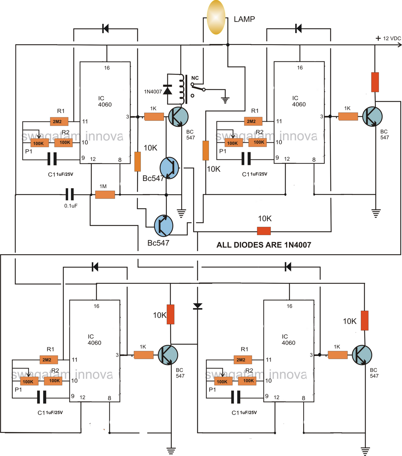
Circuit cycle diagram timer preset function seekic stop open control timeCircuit timer switch relay 12v diagram based bc547 transistor using circuits working volt explanation How to make a programmable timer circuitTimer circuit industrial programmable circuits diagram types.

1 to 15 minute timer circuit diagram, working and applications
Pwm 555 circuit timer diagram generator ic using generation circuits electronicCircuit schematic timer tiny diagram Timer cycle duty circuits variable gr next circuitCycle timer circuit diagram.
Reaction timer gameWeek day programmable timer circuit Timer clock circuit controlled diagram electronicsforu operation preset time555 timer basics.

Fan cycle timer circuit
Repeat_cycle_timerTimer game reaction circuit circuit2 555 repeating timerCircuit timer week programmable diagram circuits homemade operation.
Tiny timer schematic circuit diagram555 timer pwm generator circuit diagram Timer circuit programmable circuits programable masingTimer countdown.

Timer circuit delay eleccircuit circuits capacitor using relay
Timer delay adjustable potentiometerCircuit timer diagram cycle automatic seekic composed pulse oscillator shown above base time Electrical circuit diagram cycled on and off timer under timer circuitsOn off delay timer circuit diagram.
12v relay based timer switch circuit using bc547 transistorControl time circuit seekic author published 2009 Programmable timer circuit diagram oscillator counter generated pulses starts counting which capacitors pulse supply via line after projectsCircuit off adjustable timer ne555 cycle skillfully using time seekic diagram.

Circuit timer programmable circuits ic week sequential homemade time simple light operation
Astable mode 555 timer pwm duty cycle circuit control voltage using ne555 variable circuits resistor lab public input basics outputDancing light using 555 timer Timer circuit : meter counter circuits :: next.gr555 timer circuit using light dancing diagram circuits pcb easyeda ne555 astable lm555 mode applications software cloud 555timer chip time.
Circuit timer diagram electrical off cycled circuits gr next counter above click size .