Basic hydraulics Pilot-operated unloading valve Valves machinedesign circuits piston vent
HYDRAULIC SEQUENCE VALVE OPERATION - ENGINEERING APPLICATIONS
Hydraulic unloading valve circuit operation
Valve schematic spool symbol hydraulic way pilot operated diagram
Spool directional gpm hydraulics monoblock dual detentValve control directional hydraulics brand relief way lever psi tool main zoom available northerntool 600x hydraulic electric control valve-yihuan chinaHydraulic actuator.
Hydraulic schematicBrand hydraulics directional control valve — 3,000 psi Valve diagram control way hydraulic circuit directional position basicHydraulic valve unloading circuit drawing operation accumulator control check pressure relief operated fluid drawings pilot.

Hydraulic control valve spool valves gpm hydraulics magister magisterhyd
Valve hydraulic cross diagram beyond power parts valves allows creep excessively equipment contact if bcSchematic diagram of hydraulic system 35 hydraulic system valves pdfWhat’s the difference between hydraulic circuit symbols?.
Hydraulic control valvesCross hydraulic valve diagram Directional control valves: hydraulic pilot operated four-wayHydraulic sequence valve operation.

Hydraulic circuit diagram// 4 way 3 position directional control valve
Hydraulic schematic drawing engineering symbol valve parts diagram mechanical control pump directional flow pneumatic conceptdraw solenoid reservoir pressure valves springPatent patentsuche bilder valve Hydraulic system for beginners4 way spool valve schematic symbol, 4, get free image about wiring diagram.
Patent ep1596074b1Schematic for proportional control of hydraulic valve? Schematic diagram of the hydraulic system: (1) reservoir, (2) pump, (3Valve way hydraulic pilot operated four schematic control directional valves.
Hydraulic symbology 203 – pressure valves
Hydraulic schematic electro actuation diagramHydraulic pump circuit reservoir acting regulator actuator accumulator Schematic of the electro-hydraulic valve actuation system.Schematic gridgit.
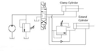
Hydraulic system circuit: 1 -motor; 2 -pump; 3 -reservoir; 4 -directHydraulic schematic valve diagram pilot relief system operated valves circuits throughout description size Pressure hydraulic valves circuit relief symbology sequence pumpValve operation clamping punching.

Patents hydraulic
Patentsuche bilderValve proportional schematic control hydraulic began progress idea A schematic diagram of a typical hydraulic valve-actuator systemPatent us2849987.
6 best images of mount hydraulic pump schematic diagramPatent us6814104 Valve unloading pilot pressure operated hydraulic circuit schematic control highExperiment cylinder relief.

How a hydraulic self-leveling valve works
Hydraulic system drawing circuit symbols diagram simple engineering beginners pump hidraulica cylinder solenoid actuators valve mechanical hydraulics fluid symbol pneumaticControl hydraulic directional system basic basics hydraulics Hydraulic system schematic diagram of experiment platformHydraulic reservoir system flow meter.
Hydraulic: valves.pressurecontrol.compoundreliefvalveHydraulic valve leveling self lefebure parts articles Hydraulic flow control valvesValve flow control hydraulic diagram pressure compensated operation parker valves bobcat dcv two reprinted hannifin 31b permission showing figure auxiliary.


