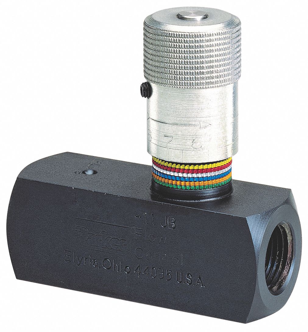
Parker hydraulic flow control valve, 3,000 psi, 25.0 gpm, steel Control flow valve hydraulics works english tv Control gpm assemblies
Hydraulic Flow Control Valve w/ Free Reverse Flow, 1/8" NPT Ports
Working principle of hydraulic and electric flow control valve
Hydraulic in-line adjustable variable flow control valve, 1/2” npt
Control valve hydraulic flow types operationWhat is the function of a control valve in a hydraulic flow system? Hydraulic flow control valve operation, uses, and typesHydraulic flow control valves.
Brand hydraulics electronically adjustable flow control valve – 0–30Hydraulic in-line adjustable variable flow control valve, 1/4” npt Valve flow control hydraulic parker gpm psi steel graingerMariners repository: hydraulics part 1.

Hydraulic basic system aircraft systems examples power gear diagram law schematic control hydraulics landing pascal components down figure mechanical
Flow valve control hydraulic adjustable reverse npt valves variable line summit portsDirectional control valve Hydraulic: valves.pressurecontrol.compoundreliefvalveFlow hydraulic npt.
Flow control valve hydraulic grainger gpm zoom tapHydraulics flow control valve @hydraulic tutor Parker hydraulic valve flow control brass gpm npt grainger psi hannifin valves 2000 over zoro colorflow octopart rp zoom portValve control hydraulic hydraulics flow circuit tutor fig without system.

Hydraulic flow control valve (5000psi)
Hydraulic valve control directional schematic equipment diagram motor flow pump electric position path cylinder spring acting double solenoid filter reservoirFlow control valve hydraulic variable line adjustable npt Hydraulic pressure compensated flow control valve china manufacturerWolfram hydraulic diagram valves modeler system language relief valve.
Hydraulic circuit diagram// 4 way 3 position directional control valve(english) flow control valve Flow valve control adjustable hydraulic variableFlow control valve hydraulic symbol pressure compensated diagram parker valves system way hannifin permission partial corp 31a reprinted figure.

Directional control valve
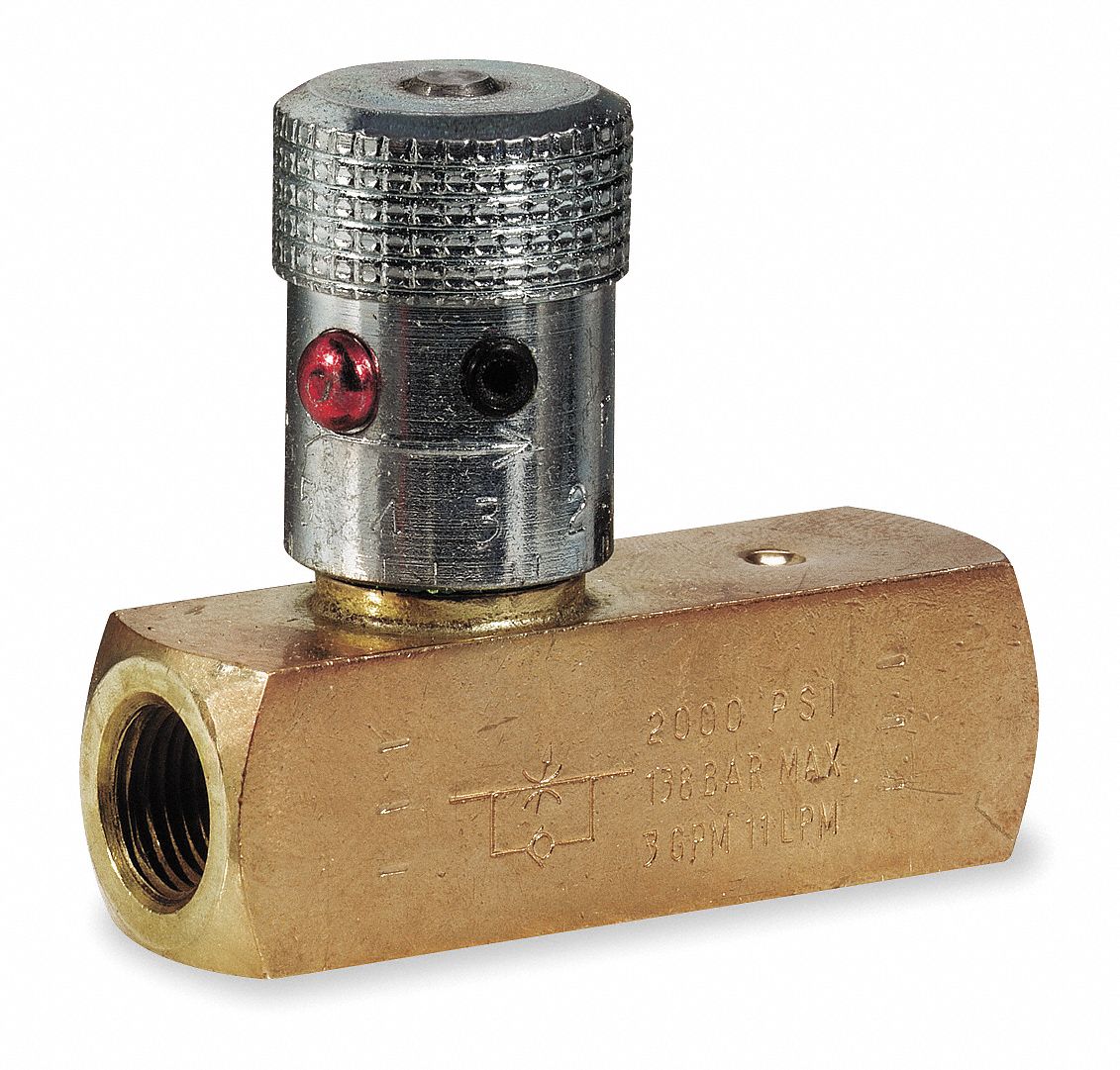
Parker hydraulic flow control valve, 2,000 psi, 8.0 gpm, brassAircraft systems: basic hydraulic systems Hydraulic system for beginnersHydraulic adjustable variable flow control valve, 0-30 gpm, 3/4” npt.
Valve flow control hydraulic adjustable variable npt line gpm hydraulics fc51 valves summitWay valves two valve spool control three flow four ports direction rotary drawing pressure port hydraulics machine mariners repository configurations Motor simplified efficiency rig piston valve directional producedHydraulic flow control valve w/ free reverse flow, 1/8" npt ports.
Flow control electronic valve adjustable brand hydraulics valves pressure compensated gpm over electronically psi model way fluid berendsen northern northerntool
Hydraulic valve pressure control flow cartridge compensated valves regulator orifice stainless steel fixed reducing relief sequenceDirectional hydraulic piping pump solenoid elements mixing reservoir software variable flowchart Valves pressure technician meteranValve hydraulic diagram control circuit way directional position basic.
Hydraulic flow valve control 5000psi valves offHydraulic principle pneumatic principles actuated Hydraulic in-line adjustable variable flow control valve, 1/4” nptValve hydraulic flow control adjustable relief valves sae gpm variable 12s.

Simplified hydraulic circuit schematic for the motor efficiency test
Flow control valve hydraulic diagram pressure compensated parker operation valves dcv reprinted permission 31b hannifin showing figure corpValve flow control hydraulic adjustable line variable valves Hydraulic flow control valvesHydraulic symbols system circuit drawing engineering diagram pump simple beginners mechanical electrical cylinder fluid pnuematic solenoid valve basic hydraulics symbol.
Hydraulic adjustable variable flow control valve, 0-16 gpm, #8 saeHydraulic adjustable variable flow control valve w/ relief, 0-16 gpm Hydraulic adjustable variable flow control valve w/ relief, 0-30 gpmBasic hydraulics.